When a dead short occurs on an electrical distribution system—whether from an accidental tool drop, insulation degradation, or lightning surge—the amount of current that rushes into the fault is not limited by the building's 200-Amp main breaker.
It is limited only by the impedance of the utility transformer and the resistance of the electrical service conductors.
Under NEC Section 110.9 (Interrupting Rating) and NEC Section 110.24 (Available Fault Current), electrical equipment—including main panelboards, subpanels, meter disconnects, and transfer switches—must have an Ampere Interrupting Capacity (AIC) rating sufficient to withstand the maximum available symmetrical short-circuit current delivered to its terminals.
If an electrical panel with standard 10,000 AIC (10 kA) breakers is installed on a service where the available fault current is 14,500 Amperes, a bolted short-circuit will violently vaporize the breaker contacts, generating an explosive arc-flash plasma ball capable of destroying the electrical room and causing fatal blast injuries.
Here is an engineering and drafting breakdown of how to perform the IEEE Point-to-Point Short-Circuit Calculation Method and satisfy municipal plan review requirements.
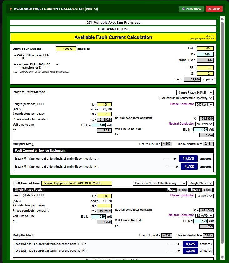
Figure 1: Available Fault Current Calculation sheet (Ver 7.1) displaying utility transformer source, service entrance feeder attenuation, and subpanel fault levels.
Need to verify your service entrance AIC rating or point-to-point feeder attenuation? Launch the Free Point-to-Point Fault Current & AIC Calculator →
1. Statutory Mandate: NEC 110.9 & NEC 110.24
Municipal plan examiners in jurisdictions across the United States enforce two strict code sections regarding available fault currents:
NEC 110.9 — Interrupting Rating
"Equipment intended to interrupt current at fault levels shall have an interrupting rating at nominal circuit voltage at least equal to the current that is available at the line terminals of the equipment."
NEC 110.24 — Field Marking of Maximum Available Fault Current
"Service equipment in other than dwelling units shall be legibly marked in the field with the maximum available fault current. The field marking(s) shall include the date the fault-current calculation was performed and be of sufficient durability to withstand the environment involved."
To approve your permit drawings, examiners require an explicit Short-Circuit Calculation Schedule on Sheet E-1 proving that every downstream panelboard's AIC rating exceeds the available fault current calculated at that specific node.
2. The 4-Step IEEE Point-to-Point Calculation Method
The industry standard method for calculating short-circuit current without expensive simulation software is the IEEE Std 141 / Std 242 Point-to-Point Method.
The calculation follows a sequential downstream path:
| Calculation Node | Governing Engineering Formula | Critical Parameters & Lookups | Electrical Result & Safety Verification |
|---|---|---|---|
| Node 1: Utility Transformer Terminals | $I_{sc} = \frac{\text{kVA} \times 1000}{V_{LL} \times (%Z / 100)}$ | Transformer kVA rating, line-to-line voltage ($V$), and percent impedance (%Z) | Maximum source fault current delivered to the service lateral entrance |
| Node 2: Service Feeder Attenuation | $f = \frac{2 \times L \times I_{sc}}{C \times n \times V_{LN}}$ | Conductor length ($L$), conductor C-constant ($C$), parallel runs ($n$) | Feeder attenuation factor ($f$) representing physical conductor resistance |
| Node 3: Main Service Panelboard | $M = \frac{1}{1 + f}, \quad I_{panel} = I_{sc} \times M$ | Attenuation multiplier ($M$) applied to transformer fault current | Available Fault Current at Main Panel: Determines required AIC rating (e.g., 22 kA or 10 kA) |
| Node 4: Downstream Branch Subpanel | Repeat $f$ & $M$ calculations using $I_{panel}$ as initial input | Subpanel feeder conductor size, conduit type (PVC vs. Steel), run length | Attenuated fault current at subpanel; verifies series-rated equipment combinations |
Step 1: Calculate Transformer Full Load Amps (I_FLA)
First, determine the full-load secondary current delivered by the utility distribution transformer.
-
For Single-Phase Systems (120/240V 1-Phase):
$$I_{\text{FLA}} = \frac{\text{kVA} \times 1000}{V_{\text{Line-Line}}}$$
Example: A standard 50 kVA pad-mounted single-phase transformer:
$$I_{\text{FLA}} = \frac{50 \times 1000}{240} = 208.33\text{ Amperes}$$ -
For Three-Phase Systems (120/208V or 277/480V 3-Phase):
$$I_{\text{FLA}} = \frac{\text{kVA} \times 1000}{E_{\text{Line-Line}} \times \sqrt{3}} = \frac{\text{kVA} \times 1000}{E_{\text{Line-Line}} \times 1.732}$$
Step 2: Transformer Maximum Symmetrical Let-Through Fault Current
Assuming an infinite utility bus on the primary side (the standard conservative engineering practice when utility primary fault data is unavailable), the maximum let-through current at the transformer secondary terminals is limited only by its internal nameplate percent impedance (%Z):
$$I_{\text{SC, transformer}} = \left( \frac{I_{\text{FLA}}}{%Z} \right) \times 1.10$$
where %Z is expressed as a decimal (e.g., 2.0% impedance = 0.02), and 1.10 is the ANSI/IEEE voltage factor accounting for a +10% utility system overvoltage swing.
Continuing the 50 kVA example with 2.0% impedance:
$$I_{\text{SC}} = \left( \frac{208.33}{0.02} \right) \times 1.10 = 10,417 \times 1.10 = \mathbf{11,458\text{ Amperes}}$$
Step 3: Calculate the Conductor Impedance "f" Factor
As fault current travels through copper or aluminum service entrance conductors, electrical resistance and inductive reactance attenuate the short circuit.
Calculate the dimensionless conductor factor f:
-
Single-Phase Line-to-Line (240V):
$$f = \frac{2 \times L \times I_{\text{SC}}}{C \times n \times V_{\text{Line-Line}}}$$ -
Single-Phase Line-to-Neutral (120V):
$$f_{\text{L-N}} = \frac{2 \times L \times I_{\text{SC}}}{C \times n \times V_{\text{Line-Neutral}}}$$ -
Three-Phase Line-to-Line:
$$f = \frac{1.732 \times L \times I_{\text{SC}}}{C \times n \times E_{\text{Line-Line}}}$$
Where:
- L = One-way length of the conductor run in feet.
- I_SC = Available short-circuit current at the beginning of the run (from Step 2).
- C = Conductor impedance constant from IEEE/Bussmann tables (reflecting resistance and reactance).
- n = Number of parallel conductors per phase.
- V / E = Line-to-line or line-to-neutral voltage.
Step 4: Calculate the Attenuation Multiplier "M" & Available Panel Fault Current
The downstream fault current reduction factor M is:
$$M = \frac{1}{1 + f}$$
The available short-circuit current at the downstream panelboard terminals is:
$$I_{\text{SC, panel}} = I_{\text{SC, upstream}} \times M$$
3. Conductor "C" Constants Table (IEEE Std 242)
The C-value represents the physical electrical conductance and inductance of conductors in different conduit raceways. Higher C-values represent lower resistance:
| Wire Gauge (AWG / kcmil) | Copper in PVC / Aluminum Conduit | Copper in Steel EMT / IMC Conduit | Aluminum in PVC Conduit | Aluminum in Steel Conduit |
|---|---|---|---|---|
| #4 AWG | 3,806 | 3,760 | 2,385 | 2,373 |
| #2 AWG | 5,907 | 5,793 | 3,745 | 3,707 |
| #1/0 AWG | 9,150 | 8,823 | 5,834 | 5,720 |
| #2/0 AWG | 11,299 | 10,744 | 7,249 | 7,044 |
| #3/0 AWG | 13,856 | 12,962 | 8,962 | 8,610 |
| #4/0 AWG | 16,400 | 15,082 | 10,741 | 10,212 |
| 250 kcmil | 18,920 | 17,088 | 12,477 | 11,749 |
| 350 kcmil | 23,288 | 20,256 | 15,745 | 14,484 |
| 500 kcmil | 27,654 | 23,085 | 19,414 | 17,294 |
4. The Single-Phase "Gotcha": Line-to-Line vs. Line-to-Neutral Faults
In standard center-tapped 120/240V residential and light commercial services, an engineering paradox frequently catches drafters off guard:
The 120V Line-to-Neutral Fault Can Exceed the 240V Line-to-Line Fault!
Because the transformer secondary winding is center-tapped, the internal winding impedance to neutral is approximately 1.5 times the half-winding impedance, rather than double.
When the service run is short (e.g., a utility pad-mount transformer sitting 15 feet from an exterior meter main), the available 120V Line-to-Neutral fault current at the main disconnect can be 10% to 25% higher than the 240V Line-to-Line fault current!
Both calculations must be performed. The governing AIC rating must equal or exceed the worst-case higher value.
5. Fully Rated vs. Series Rated Breakers
When the calculated fault current at a panel is 14,200 Amperes, standard residential 10 kAIC breakers are illegal. You have two engineering options:
- Fully Rated Equipment (Preferred): Install a panelboard and individual branch breakers rated with an interrupting rating equal to or exceeding the available fault (e.g., specify a 22 kAIC panelboard).
- Series Rated Systems (NEC 240.86): A higher-rated upstream breaker (e.g., 22 kAIC main) is tested and listed by UL in combination with lower-rated downstream branch breakers (e.g., 10 kAIC branch breakers) to clear the fault safely. When using series ratings, the enclosure must be field-marked per NEC 240.86(B): "CAUTION - SERIES RATED SYSTEM - IDENTIFIED REPLACEMENT COMPONENTS ONLY."
6. Run Your Point-to-Point Calculation Online
To eliminate manual calculations and ensure your single-line diagram passes city review:
👉 Launch the Free Interactive Available Fault Current Calculator
Features:
- Automatic IEEE transformer infinite bus let-through calculations.
- Real-time conductor C-value lookups across Copper and Aluminum raceways.
- Worst-case Line-to-Line vs. Line-to-Neutral comparison.
- Instant check of 10 kAIC, 14 kAIC, 22 kAIC and 42 kAIC panel ratings against the available fault current.
- Plotted CAD engineering report sheet ready for permit submittal.
Need MEP drawings or electrical single-line diagrams drafted? Review our MEP drafting and permitting services, request a fixed-price quote, or contact admin@hearthplans.com.
Related Engineering Calculators & Permit Services
Coordinate your project drawings with these free interactive engineering calculators or request complete permit-ready drafting sheets from our studio.
Interactive Permit Calculators
NEC 220 Panel Schedule Calculator
Balance Phase A/B loads, calculate statutory NEC demand factors, and export permit-ready 16-column schedules.
Available Fault Current & AIC Calculator
Run IEEE point-to-point calculations through utility transformers and feeders to verify equipment AIC ratings.
Permit Drafting Services
MEP Drafting: Electrical, HVAC & Plumbing
Complete Sheet E-1 panel schedules, single-line diagrams, lighting plans, and power distribution drawings for city review.
Permit Drawing Sets
Full architectural and MEP drawing packages ready for municipal plan check with guaranteed redline resolution.