When submitting residential or commercial construction drawing sets to municipal building departments, few sheets receive more scrutiny from electrical plan examiners than Sheet E-1: Electrical Panel Schedules & Service Load Calculations.
A frequent mistake made by builders and junior drafters is simply adding up the numerical values printed on circuit breaker handles—or taking total nameplate ratings—and declaring that a 2,500 sq ft single-family home requires an astronomical 400-Amp or 600-Amp service entrance.
In the real world, electrical equipment does not operate simultaneously at 100% capacity. Under the National Electrical Code (NEC Article 220), electrical services, feeders, and panelboards are sized based on calculated demand load, using statutory diversity factors established through decades of empirical electrical engineering data.
Below is an authoritative engineering and drafting guide explaining how to calculate electrical panel schedules per NEC Article 220, balance phase busbars, size service feeders, and draft permit-ready CAD schedules.
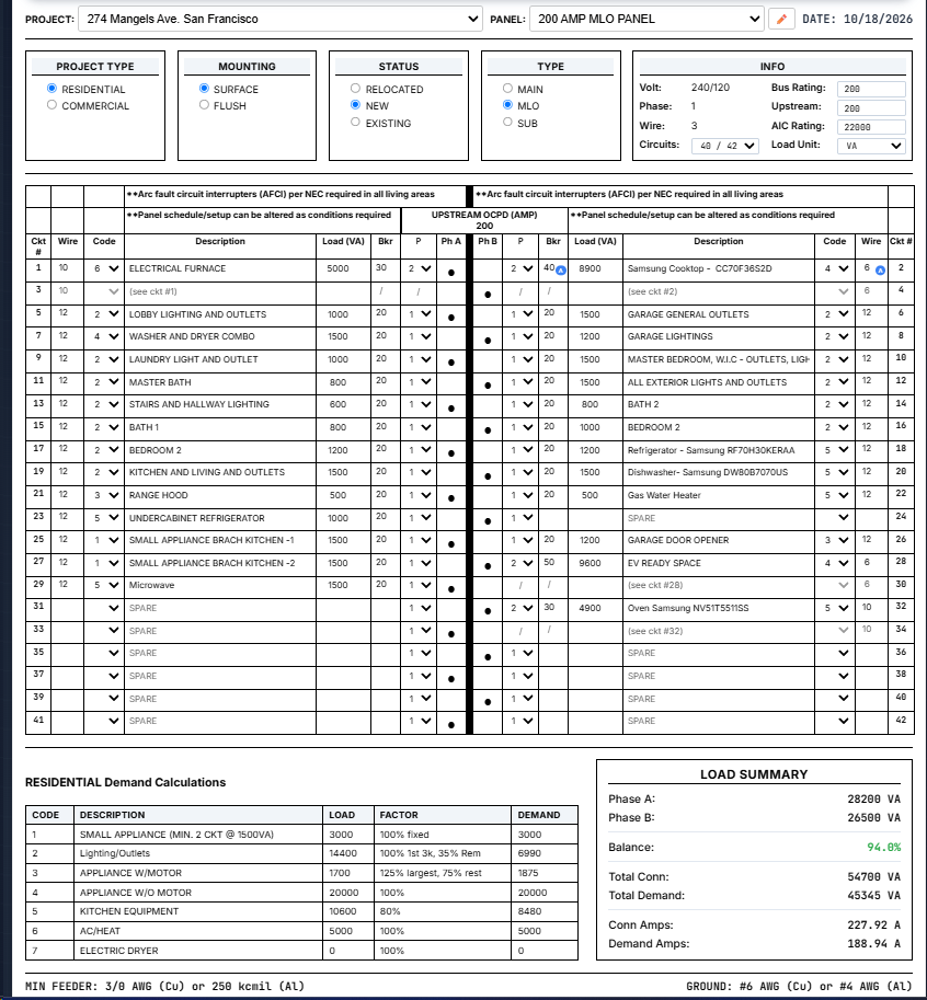
Figure 1: Full 16-column CAD electrical panel schedule generated from our engineering drafting workflow, featuring 42 circuit spaces, phase balancing, and NEC Article 220 demand calculations.
Want to calculate your own 42-space panel schedule with automatic demand factors, phase balancing, and feeder sizing? Launch the Free Interactive CAD Electrical Panel Calculator →
1. Anatomy of a Permit-Ready 16-Column CAD Schedule
A municipal electrical plan reviewer expects to see a standardized 16-column split-bus schedule representing the physical load center.
The schedule organizes branch circuits into odd-numbered slots on the left (1, 3, 5...) and even-numbered slots on the right (2, 4, 6...):
| Busbar Slot Pair (Vertical Row) | Left Bus Finger (Phase Connection) | Right Bus Finger (Phase Connection) | 240V Double-Pole Breaker Compatibility |
|---|---|---|---|
| Row 1 (Slots 1 & 2) | Slot 1: Connected to Phase A (120V) | Slot 2: Connected to Phase B (120V) | Single-pole 120V circuits to Neutral |
| Row 2 (Slots 3 & 4) | Slot 3: Connected to Phase B (120V) | Slot 4: Connected to Phase A (120V) | Slots 1 & 3 span Phase A + Phase B (240V) |
| Row 3 (Slots 5 & 6) | Slot 5: Connected to Phase A (120V) | Slot 6: Connected to Phase B (120V) | Slots 2 & 4 span Phase B + Phase A (240V) |
| Row 4 (Slots 7 & 8) | Slot 7: Connected to Phase B (120V) | Slot 8: Connected to Phase A (120V) | Slots 5 & 7 span Phase A + Phase B (240V) |
The Phase Staggering Architecture:
- Slot 1 & 2: Phase A
- Slot 3 & 4: Phase B
- Slot 5 & 6: Phase A
- Slot 7 & 8: Phase B
- This vertical alternation is why a two-pole breaker spanning slots 1 and 3 (or 2 and 4) automatically connects across Phase A and Phase B to supply 240 Volts!
Calculating Phase Unbalance Percentage:
$$\text{Unbalance (%)} = \frac{|\text{Phase A (VA)} - \text{Phase B (VA)}|}{\max(\text{Phase A}, \text{Phase B})} \times 100$$
The 10% Engineering Target: If Phase A carries 18,500 VA and Phase B carries 12,200 VA, the unbalance is 34%. Severe phase imbalance causes elevated neutral return current, excessive neutral bus heating, and unnecessary utility transformer losses. Best drafting practice is to stagger heavy 120V circuits (such as kitchen small appliances, microwave, and bathroom receptacles) across opposite phases to maintain an unbalance below 10%.
5. Feeder Conductor & Equipment Ground Sizing
Once the net demand load in Volt-Amperes is calculated, determine the minimum service entrance rating:
$$\text{Minimum Service Amps} = \frac{\text{Net Calculated Demand (VA)}}{240\text{ Volts}}$$
Under NEC Article 240.6, standard ampere ratings for circuit breakers are: 100A, 125A, 150A, 175A, 200A, 225A, 250A, 300A, 350A, and 400A. Select the standard breaker size equal to or immediately above the calculated demand amps.
Service Feeder Conductor Sizing Matrix (NEC Table 310.16 at 75°C)
| Main Breaker Rating | Copper Feeder (THHN / THWN-2) | Aluminum Feeder (XHHW-2 / SE) | Equipment Grounding Conductor (NEC 250.122) | Grounding Electrode Conductor (NEC 250.66) |
|---|---|---|---|---|
| 100 Amps | #4 AWG Cu | #2 AWG Al | #8 AWG Cu | #8 AWG Cu |
| 125 Amps | #2 AWG Cu | #1/0 AWG Al | #6 AWG Cu | #8 AWG Cu |
| 150 Amps | #1 AWG Cu | #2/0 AWG Al | #6 AWG Cu | #6 AWG Cu |
| 200 Amps | #2/0 AWG Cu | #4/0 AWG Al | #6 AWG Cu | #4 AWG Cu |
| 225 Amps | #3/0 AWG Cu | 250 kcmil Al | #4 AWG Cu | #4 AWG Cu |
| 400 Amps | (2 sets) 3/0 Cu | (2 sets) 250 Al | #3 AWG Cu | #1/0 AWG Cu |
Note: For single-phase dwelling service entrance conductors rated 100A through 400A, NEC 310.12 permits an 83% ampacity adjustment factor, allowing #4 Copper for 100A and #2/0 Copper or #4/0 Aluminum for 200A.
6. 2023 NEC Section 210.12 AFCI & 210.8 GFCI Branch Circuit Rules
Every CAD panel schedule submitted for municipal permit review must clearly indicate which circuits require Arc-Fault Circuit-Interrupter (AFCI) and Ground-Fault Circuit-Interrupter (GFCI) protection:
- AFCI Protection (NEC 210.12): Mandatory on all 120-volt, single-phase, 15- and 20-ampere branch circuits supplying outlets or devices in:
- Kitchens, family rooms, dining rooms, living rooms, parlors, libraries, dens, bedrooms, sunrooms, recreation rooms, closets, hallways, laundry areas, or similar rooms.
- GFCI Protection (NEC 210.8): Mandatory in:
- Bathrooms, garages, outdoor outlets, crawl spaces, basements, within 6 feet of sinks, boathouses, bathtubs, and shower stalls.
- Dual Protection (AFCI + GFCI): Circuits serving kitchen countertop receptacles and laundry receptacles require both AFCI and GFCI protection under the 2023 NEC.
7. Generate Your Permit-Ready CAD Panel Schedule Now
Instead of formatting complicated Excel spreadsheets or drawing lines in CAD from scratch, our free engineering web tool automates the entire process:
- Direct Inline Editing: Type circuit descriptions, loads, codes, and poles directly into the CAD schedule table.
- Automated Demand Factor Logic: Applies 2023 NEC Article 220 rules in real time.
- Real-Time Phase Balance & Feeder Sizing: Calculates Phase A vs. B totals and prints minimum feeder/ground wire callouts.
- Vector CAD Sheet Export: Print crisp 11x17 or Arch D drawing sheets directly to PDF ready for municipal permit submittal.
👉 Open the Free Interactive CAD Electrical Panel Schedule Calculator
If you need complete MEP drafting and electrical permit sets or city redline resolutions, request a fixed-price quote or email admin@hearthplans.com.
Related Engineering Calculators & Permit Services
Coordinate your project drawings with these free interactive engineering calculators or request complete permit-ready drafting sheets from our studio.
Interactive Permit Calculators
NEC 220 Panel Schedule Calculator
Balance Phase A/B loads, calculate statutory NEC demand factors, and export permit-ready 16-column schedules.
Available Fault Current & AIC Calculator
Run IEEE point-to-point calculations through utility transformers and feeders to verify equipment AIC ratings.
Permit Drafting Services
MEP Drafting: Electrical, HVAC & Plumbing
Complete Sheet E-1 panel schedules, single-line diagrams, lighting plans, and power distribution drawings for city review.
Permit Drawing Sets
Full architectural and MEP drawing packages ready for municipal plan check with guaranteed redline resolution.