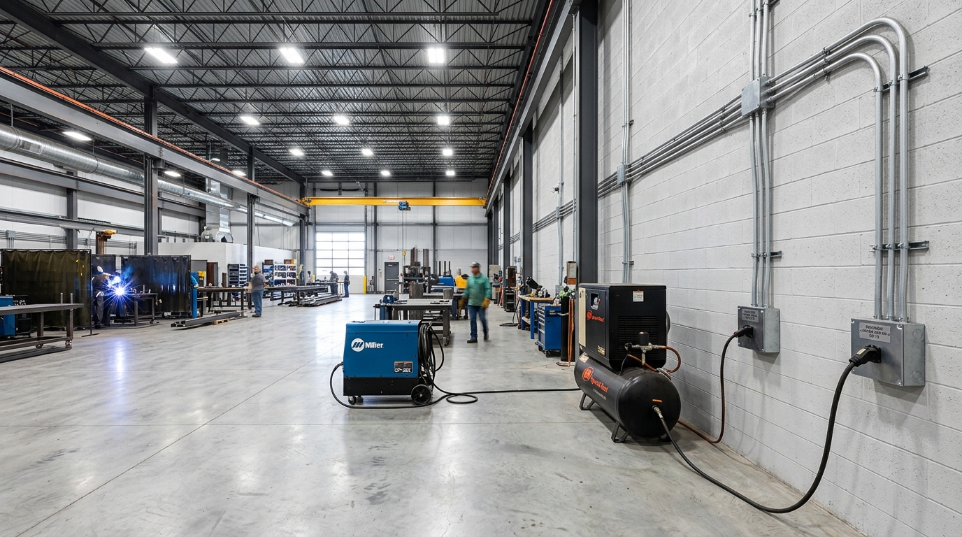
When engineering and detailing commercial MEP drafting and electrical layouts for an industrial warehouse, metal fabrication shop, or commercial auto facility, drafters encounter a unique engineering challenge that residential plans rarely face: high-drain machinery mobility.
In an active shop, fabricators cannot keep heavy equipment permanently anchored in one corner. Workers must wheel 50-Amp MIG/TIG welders, plasma cutters, and 30-Amp portable air compressors around the perimeter to work on large trailers, steel assemblies, or vehicles parked along different bays.
If you place only one outlet per circuit, workers are forced to string hazardous 50-foot heavy-gauge extension cords across the concrete floor—creating OSHA tripping hazards, vehicle pinch points, and severe voltage drops.
Conversely, if you dedicate a separate 50A circuit to every single wall location, the electrical service panel will require dozens of expensive double-pole breakers and massive main service gear for machines that will never operate simultaneously.
The engineering solution is a Perimeter Plug System under NEC 210.23(C).
Here is how to design, circuit, label, and draft an industrial warehouse perimeter power layout that passes municipal commercial plan checks with zero redlines.
1. The Code Foundation: NEC 210.23(C) for Non-Dwelling Units
In residential occupancies, strict rules limit multi-outlet branch circuits for heavy appliances. However, in commercial and industrial non-dwelling units, the National Electrical Code provides deliberate design flexibility:
NEC Article 210.23(C) — 40- and 50-Ampere Branch Circuits
Under NEC 210.23(C), a 40- or 50-Ampere branch circuit in a non-dwelling unit is explicitly permitted to supply:
- Multiple cooking appliances in commercial kitchens.
- Multiple heavy industrial receptacle outlets for mobile equipment.
Branch Circuit & Receptacle Distribution Matrix
| Circuit & Equipment Tag | Overcurrent Device | Conductor & Conduit Specification | Receptacle Type | Wall Location & Elevation | Engraved Faceplate Keynote |
|---|---|---|---|---|---|
| Circuits 2, 4 (Welder System) | 2-Pole 50A Breaker | 2 #6 AWG THHN Cu + 1 #10 Ground in 1" EMT | NEMA 6-50R (50A, 250V) | North Wall Bay 1 (+48" AFF) | "PANEL B - CKT 2,4 - DO NOT OPERATE SIMULTANEOUSLY" |
| Circuits 2, 4 (Welder System) | Shared with above | 2 #6 AWG THHN Cu + 1 #10 Ground in 1" EMT | NEMA 6-50R (50A, 250V) | East Wall Bay 3 (+48" AFF) | "PANEL B - CKT 2,4 - DO NOT OPERATE SIMULTANEOUSLY" |
| Circuits 6, 8 (Compressor) | 2-Pole 30A Breaker | 2 #10 AWG THHN Cu + 1 #10 Ground in 3/4" EMT | NEMA 6-30R (30A, 250V) | South Wall Bay 2 (+48" AFF) | "PANEL B - CKT 6,8 - PORTABLE AIR COMPRESSOR ONLY" |
| Circuits 10, 12 (Plasma Cutter) | 2-Pole 50A Breaker | 2 #6 AWG THHN Cu + 1 #10 Ground in 1" EMT | NEMA 6-50R (50A, 250V) | West Fabrication Wall (+48" AFF) | "PANEL B - CKT 10,12 - PLASMA CUTTING STATION" |
By connecting multiple NEMA 6-50R outlets to a single branch circuit, the shop crew can unplug a welder from the North wall, roll it to the East bay, and plug it in immediately—without needing extension cords.
2. Receptacle Hardware, Sizing & Mounting Heights
For commercial metal fabrication and warehouse utility walls, specify the following standard configurations on your equipment schedules:
A. Welder Circuits (Tag: W1, W2)
- Receptacle Type: NEMA 6-50R (50-Amp, 250-Volt, 2-Pole, 3-Wire Grounding).
- Conductor Sizing: #6 AWG THHN/THWN-2 Copper with #10 AWG bare copper equipment grounding conductor.
- Overcurrent Protection: 2-Pole 50A circuit breaker.
- Conduit: Minimum 3/4″ or 1″ EMT (Electrical Metallic Tubing) surface-mounted to block walls.
B. Industrial Air Compressors (Tag: AC1, AC2)
- Receptacle Type: NEMA 6-30R (30-Amp, 250-Volt, 2-Pole, 3-Wire Grounding).
- Conductor Sizing: #10 AWG THHN/THWN-2 Copper with #10 AWG copper ground.
- Overcurrent Protection: 2-Pole 30A circuit breaker.
- Conduit: Minimum 3/4″ EMT.
C. The +48″ AFF Industrial Mounting Rule
On residential plans, receptacles are mounted at +12″ to +18″ above finished floor. In an industrial warehouse, mount all 240V/250V heavy equipment receptacles at +48 inches A.F.F. (centerline):
- Moisture Protection: Keeps high-voltage plugs well clear of floor sweeping, washdown water, and spilled shop fluids.
- Impact Safety: Protects heavy junction boxes from pallet jacks, rolling carts, and forklift tire bumps.
- Worker Ergonomics: Allows shop operators to plug and unplug heavy industrial twist-lock and straight-blade cords at waist height without bending.
3. Mandatory Keynotes & Engraved Phenolic Labeling
To ensure the plan reviewer approves shared branch circuits without flagging potential overloads, drawings must demonstrate how simultaneous use is prevented in the field.
Incorporate the following exact general equipment notes onto Sheet E-1.0 (Legend & Schedules) and Sheet E-2.0 (Power Plan):
Mandatory Plan Keynote
KEYED NOTE [W/AC]: WAREHOUSE PERIMETER POWER & EQUIPMENT PLUG SYSTEM
- SCOPE: PROVIDE 250V SURFACE-MOUNTED INDUSTRIAL RECEPTACLES MOUNTED AT +48" A.F.F. (NEMA 6-50R FOR WELDERS; NEMA 6-30R FOR AIR COMPRESSORS). MULTIPLE OUTLETS ARE CONNECTED TO SINGLE BRANCH CIRCUITS AS INDICATED ON PANEL SCHEDULE TO PERMIT EQUIPMENT MOBILITY ACROSS BAYS.
- PERMANENT LABELING: CONTRACTOR SHALL PROVIDE PERMANENT ENGRAVED LAMIROID / PHENOLIC PLASTIC LABELS (BLACK WITH WHITE LETTERING) RIVETED OR ADHERED TO EACH FACEPLATE INDICATING SOURCE PANEL AND CIRCUIT NUMBER (E.G., "PANEL B - CKT 2,4").
- OPERATIONAL DIVERSITY NOTICE: SYSTEM IS DESIGNED FOR THE OPERATION OF ONLY ONE (1) WELDER OR AIR COMPRESSOR PER BRANCH CIRCUIT AT A TIME. FACEPLATE LABELS SHALL EXPLICITLY STATE: "DO NOT OPERATE MULTIPLE UNITS ON THIS CIRCUIT SIMULTANEOUSLY."
- CONDUCTORS: PROVIDE #6 AWG COPPER FOR 50A CIRCUITS AND #10 AWG COPPER FOR 30A CIRCUITS IN SURFACE-MOUNTED EMT CONDUIT.
4. Drafting Panel Schedules & Load Calculations
When building the panel schedule for an industrial shop, diversity factors must reflect actual operations:
- Nameplate vs. Duty Cycle (NEC Article 630): For arc welders, NEC 630 allows conductor sizing and demand calculations to incorporate the welder's operational duty cycle multiplier (e.g., 0.71 for 50% duty cycle, 0.63 for 40% duty cycle). This prevents over-sizing main service transformers for machines that only draw peak current during active arc striking.
- Continuous Compressor Loads (NEC 430): Motor-driven air compressors that cycle automatically are treated as continuous loads, requiring circuit conductors and overcurrent protection to be sized at 125% of motor full-load amperes (FLA).
Related Engineering Calculators & Permit Services
Coordinate your project drawings with these free interactive engineering calculators or request complete permit-ready drafting sheets from our studio.
Interactive Permit Calculators
NEC 220 Panel Schedule Calculator
Balance Phase A/B loads, calculate statutory NEC demand factors, and export permit-ready 16-column schedules.
Available Fault Current & AIC Calculator
Run IEEE point-to-point calculations through utility transformers and feeders to verify equipment AIC ratings.
Permit Drafting Services
MEP Drafting: Electrical, HVAC & Plumbing
Complete Sheet E-1 panel schedules, single-line diagrams, lighting plans, and power distribution drawings for city review.
Permit Drawing Sets
Full architectural and MEP drawing packages ready for municipal plan check with guaranteed redline resolution.